The cable fits. The connector does not. Apparently, the connector did not read the CAD drawing.
That is the problem behind this Nora3D design study: adapt an existing cable-routing part by enlarging two ports and adding a wider side entrance, while keeping its 100 × 66 × 30 mm outer dimensions. The result is an editable, saved CAD concept. It has not been printed or tested with a specific cable.
Two routing problems, two different changes
A closed opening has to accommodate whatever must pass through it. For a cable with an attached connector, sizing a hole around the cable alone may leave the connector stuck outside. Enlarging the opening addresses that clearance problem.
Side access changes the installation route. Instead of threading a connector through a closed opening, the design explores bringing the cable in from an edge. That choice creates another question: what will keep the cable from leaving through the same opening?
This is the kind of work I want Nora3D to make easier: keep a useful starting part, change the features that matter to its intended use, and leave the result open to inspection and another revision.
Start with a template, then add editable features
We inserted the Dual-port cable bulkhead adapter from Nora3D's template library into a dedicated document. The body included two through-holes, four mounting holes, reinforcing details and a recessed front panel.
The inserted template did not expose its original dimensions as editable parameters in this session. We added new cutting features—two cylinders and a rectangular slot—and subtracted them from the inserted solid. The parameters in this example belong to those new features; they are not recovered template history.
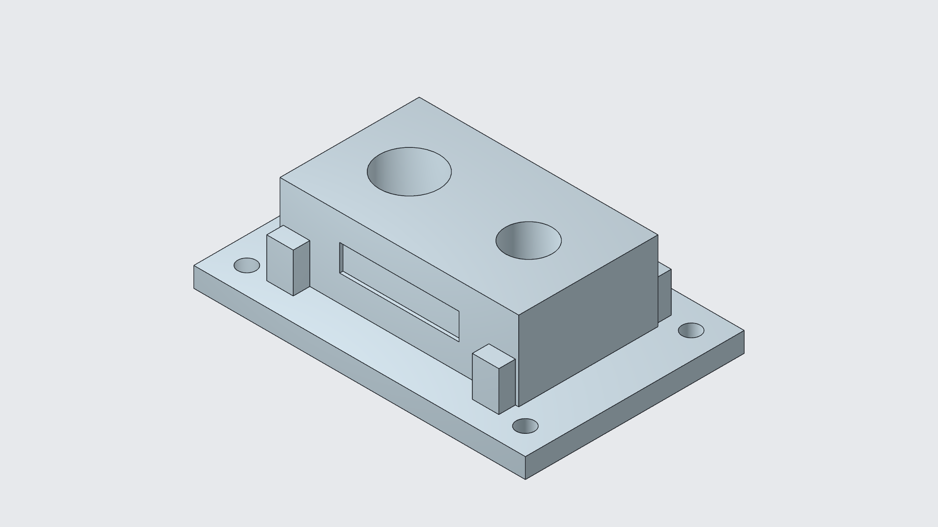
Save the baseline before enlarging the ports
First, we saved a baseline with the smaller port openings and a narrow side cut. Then we changed the port sizes, saved again, and widened the side entrance in a separate step.
| Editable feature | Saved baseline | Revised design |
|---|---|---|
| Left port diameter | 20 mm | 28 mm |
| Right port diameter | 16 mm | 22 mm |
| Side entrance width | 4 mm | 12 mm |
| Outer dimensions | 100 × 66 × 30 mm | Unchanged |
The port cutters are driven by radii: 10 → 14 mm on the left and 8 → 11 mm on the right. All three cuts extend through the 30 mm body. These are demonstration dimensions, not measurements taken from a particular connector or cable.
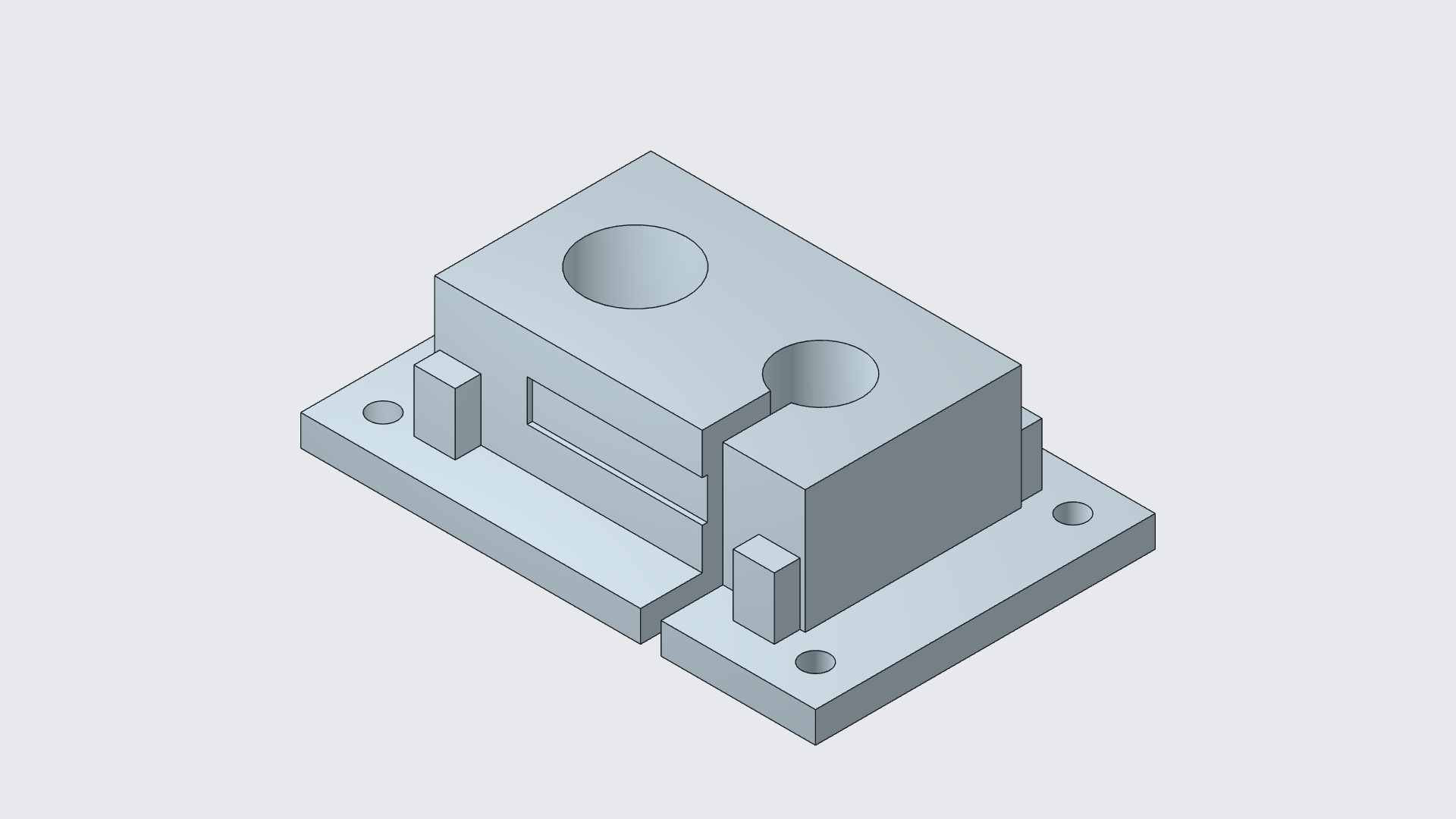
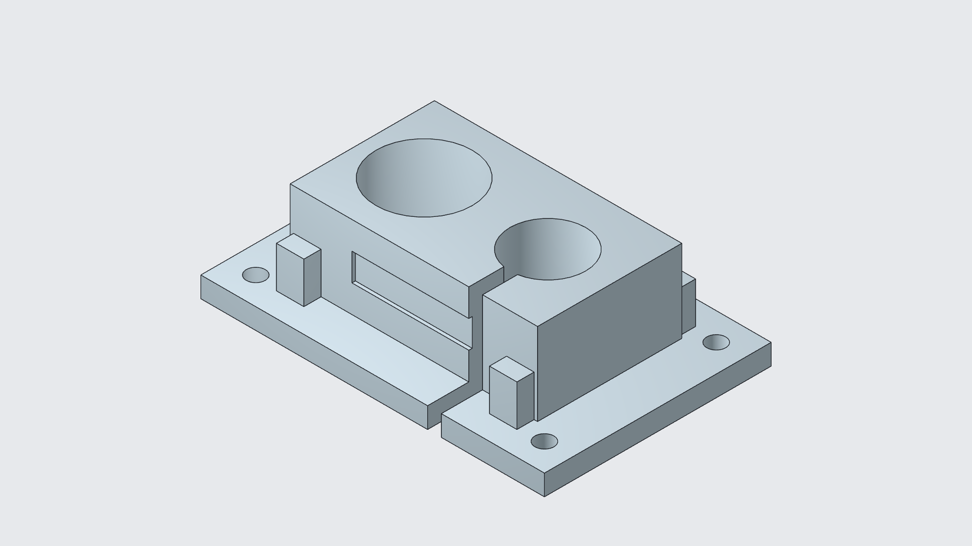
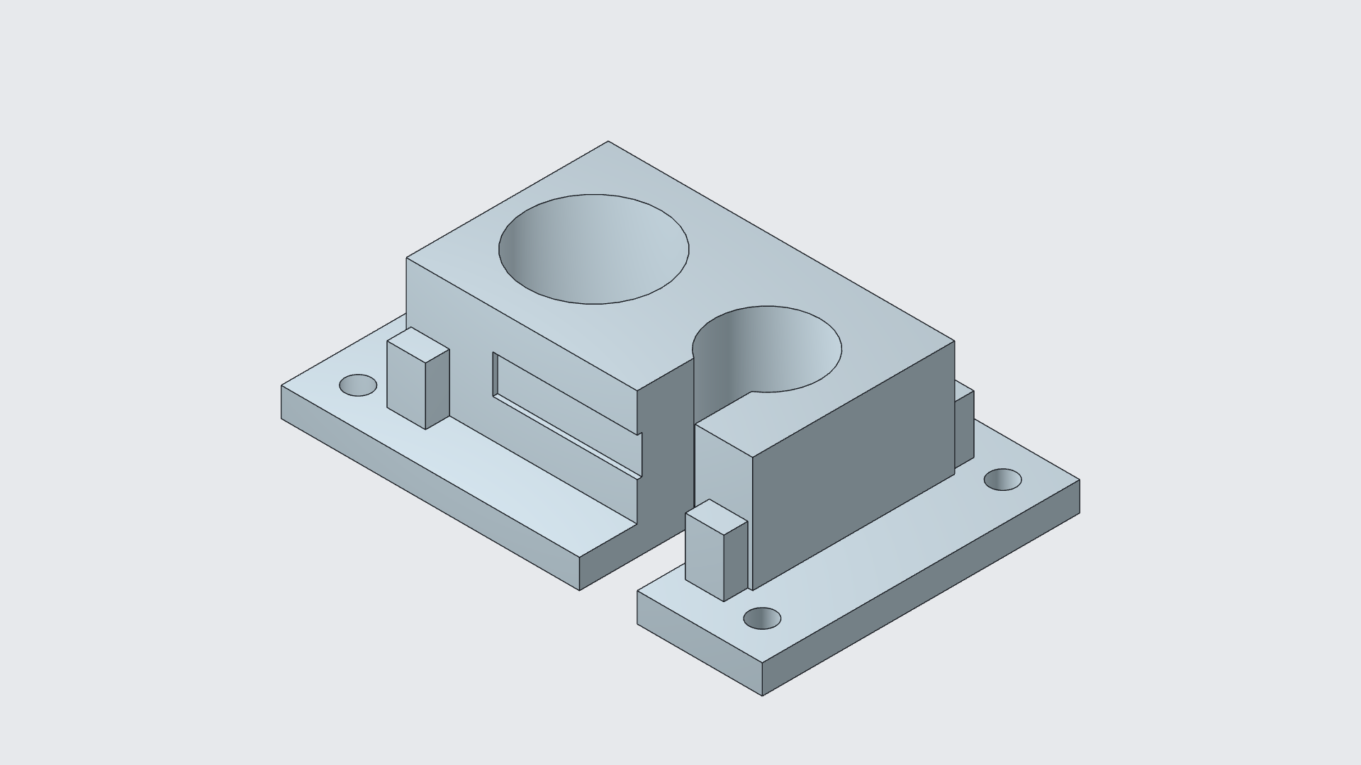
The larger ports and the wider slot are separate decisions. A different connector may need more clearance; a different installation may need side access. Keeping those choices editable makes the next revision specific rather than a complete redraw.
The slot also interrupts the original front recess. Preserving the outer dimensions does not mean every original detail remains unchanged.
What survived saving and reopening?
After reopening the saved document, the revision, feature identities and seven new driving dimensions matched the saved state. Native kernel bounds and volume also matched within numerical precision. The geometry check reported a valid, closed solid.
That evidence supports a useful, limited conclusion: the revised CAD design remained available for further work. It does not prove complete B-rep equivalence, physical fit, manufacturing quality or a reliable cable-retention mechanism.
From editable CAD to a part worth trial-fitting
The next version needs a real cable, its connector dimensions and a clear installation requirement. Before treating this as a functional part, the design still needs decisions about tolerances, remaining wall thickness, print orientation, edge protection and how the cable will be retained.
An open side slot can let a cable out as well as in. This concept has no verified retention, strain relief, seal or ingress-protection rating. No physical fit test or print was performed, and this case study does not provide a validated printing file.
The routing need itself is established: icotek's split cable-entry systems address cables with attached connectors. That reference supports the use case; it does not transfer the manufacturer's performance or certifications to this model. Reference checked October 31, 2026.
For me, the useful promise of editable AI CAD is a shorter path from “this part is close” to a version you can inspect, revise and eventually trial-fit. This example completes the CAD-editing and save/reopen steps. The physical test is still ahead.
Keep working on the part
- Adapt a storage-case insert while keeping its outer dimensions.
- Change a phone dock's slot width for a different fit requirement.
- Learn about editable CAD models in Nora3D.
Open Nora3D and start with a part whose purpose you can describe. Decide what must change, what must stay, and what you will check before making it physical.