You buy one larger adapter. Somehow, the storage problem now includes everything you already own.
How can you resize a tool case insert without redesigning the case? In this Nora3D example, keep the existing case template, create a separate editable insert, and change the dimensions of its tool openings. Three round openings grow from 20 to 36 mm in diameter; one rectangular opening changes from 95 × 18 to 145 × 30 mm. The original case geometry stays unchanged.
This is a CAD design study of a different tool layout. No physical tools were fitted, and the insert has not been printed.
What stays from the case template?
The starting point is Gridfinity Storage Box, selected from Nora3D's template library. Its six solid bodies include a detailed case and detached lid. The original template's editable dimensions are not exposed in this document. The new controls belong to the added insert and pocket features, not to a recovered history of the case.
That distinction matters when you already have useful geometry. You can make an editable addition around it without claiming that every original feature has become parametric. Here, the detailed shell provides a starting point while the redesign focuses on the space allocated to tools.
The template name identifies the library item used. Compatibility with other Gridfinity parts or a particular standard has not been verified.
How is the editable insert built?
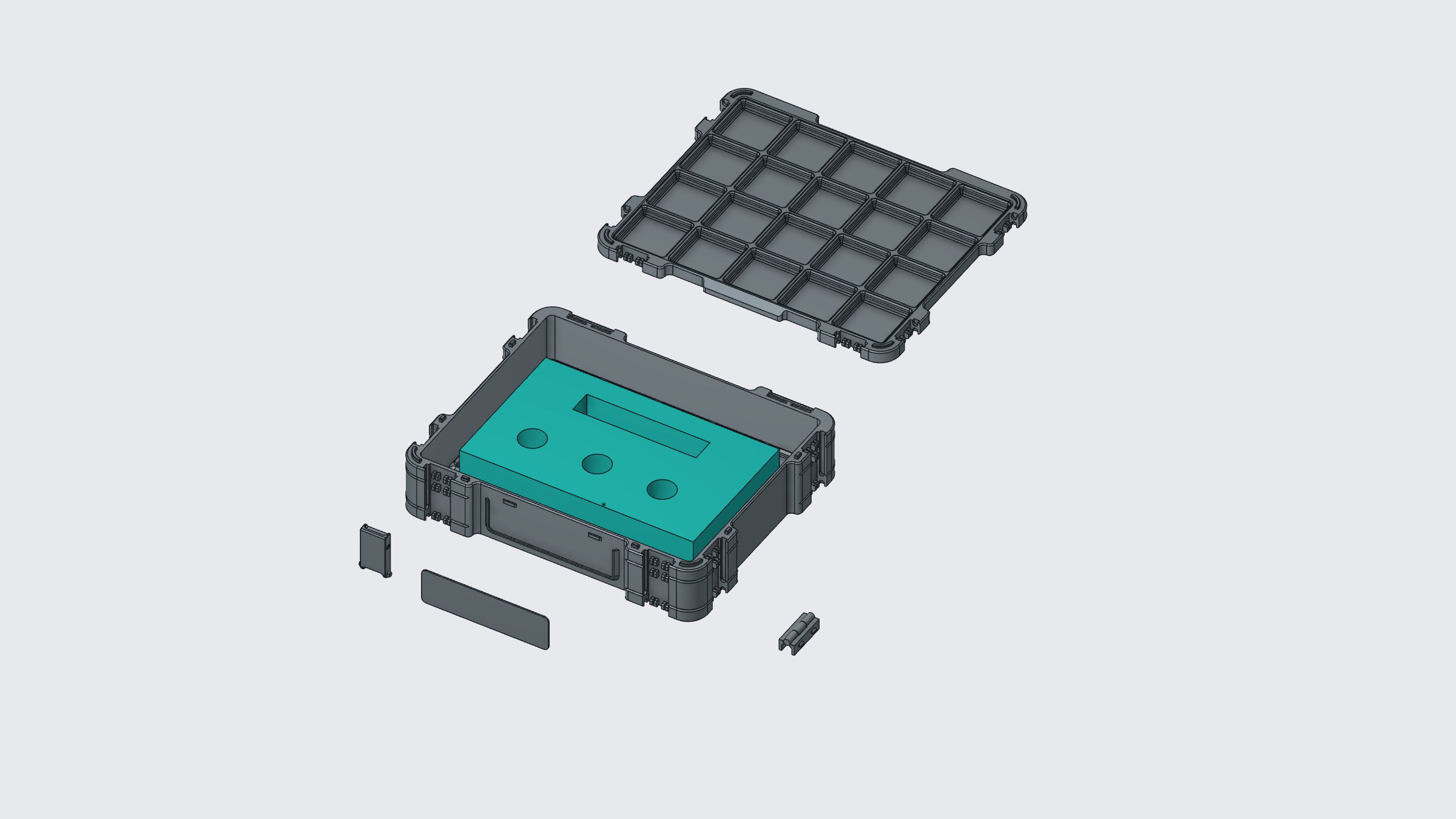
The independent insert starts as a 180 × 110 × 24 mm solid. Three cylindrical cutting bodies and one rectangular cutting body are subtracted from it to create the openings. Editing those added features changes the resulting insert.
The first layout has three 20 mm diameter round openings and a 95 × 18 mm rectangular opening. That baseline is saved before the dimensions are revised, so the comparison starts with a recorded model state.
Which dimensions change for a new tool layout?
Each round opening is controlled by a radius. Increasing all three radii from 10 to 18 mm gives three 36 mm diameter openings. The rectangular opening becomes longer and wider: 145 × 30 mm instead of 95 × 18 mm.
| Dimension | Saved baseline | Revised layout |
|---|---|---|
| Round pocket 1 radius | 10 mm | 18 mm |
| Round pocket 2 radius | 10 mm | 18 mm |
| Round pocket 3 radius | 10 mm | 18 mm |
| Long pocket length | 95 mm | 145 mm |
| Long pocket width | 18 mm | 30 mm |
These are five edits to driving parameters, not five replacement models. The insert's outer dimensions remain 180 × 110 × 24 mm. The 30 mm value describes the rectangular opening's width in the layout, not its cutting depth.
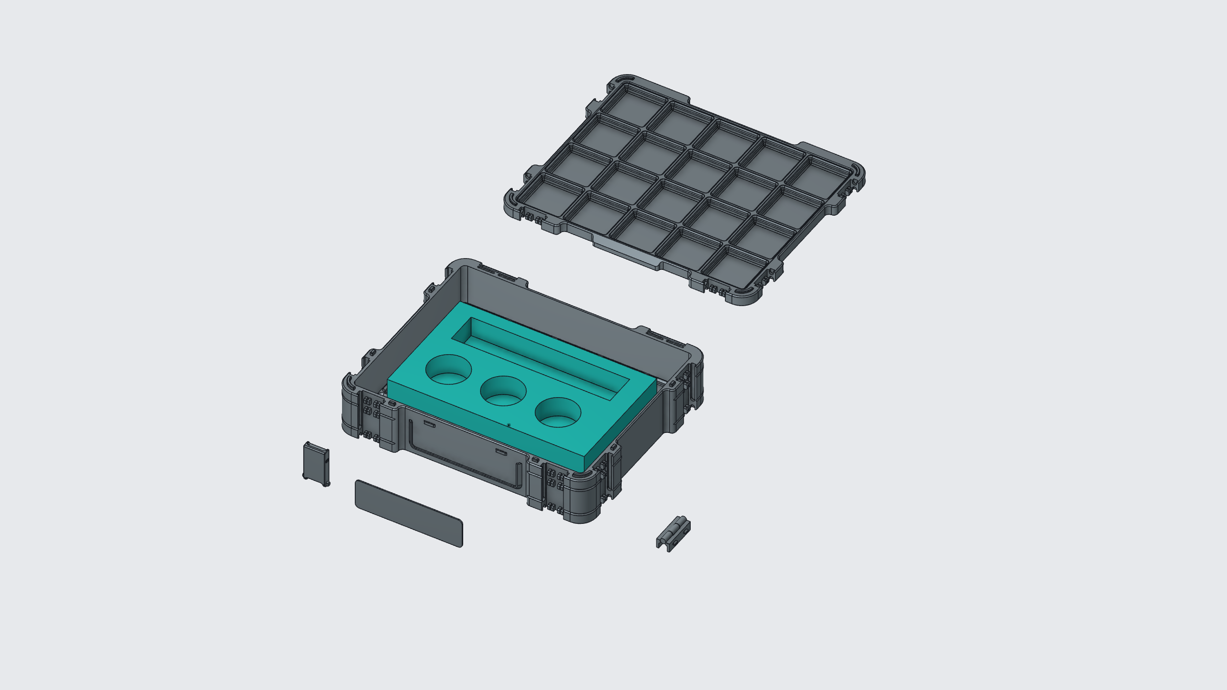
The before-and-after images use the same view to show what changed. Larger openings are one possible response to a new tool set; they are not measurements taken from real tools in this demonstration. Tool clearance still has to be chosen and checked separately.
What has been checked in the saved design?
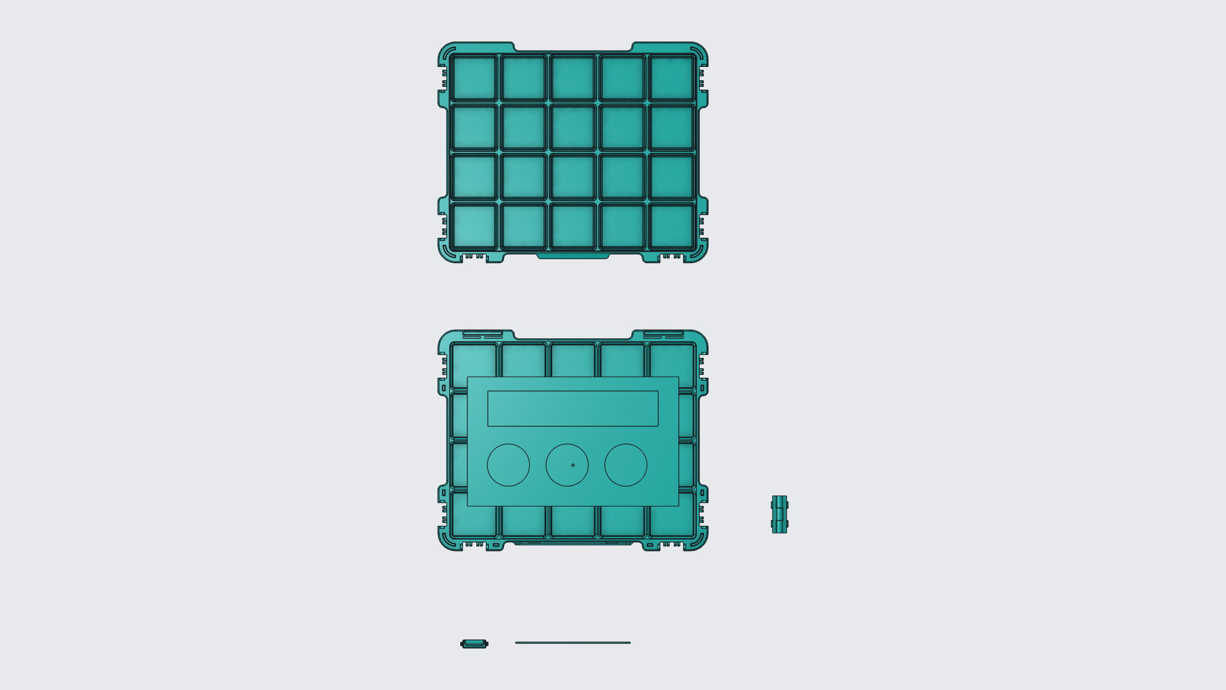
The editing session returned successful save receipts, and the parameter readback confirmed the revised values. The resulting insert was reported as a valid, closed solid. An interference check reported no overlap between the insert and the main case body.
Final save-and-reopen verification is still incomplete. The CAD page timed out during recovery. The initial template had been reopened earlier, but that does not establish that the final edited insert reopens correctly. The evidence here supports the saved editing-session result, with that later check still pending.
What is still needed before printing the insert?
No overlap with the case does not establish that the insert rests on a supported surface, stays fixed, or leaves enough space for the lid. Before a physical build, check bottom support and retention, tool clearances, lid closure, material, print orientation and tolerances, then perform a trial fit.
The detached lid and small parts are template geometry, not a verified moving assembly. This example includes no STL or STEP export and no tested printable download.
The useful idea is to keep the part of the design that still serves you and revise the part whose requirements changed. For another template-based example, see editable drawer dividers in a desk organizer. That case changes partitions; this one changes the tool openings in a separate insert.
Open Nora3D to explore the template library and decide which details your next insert needs to control.