The first model gets your attention. The next change earns your trust.
A phone stand can look convincing on screen. The useful questions come when you need a wider cable slot, a different mounting hole, or a little more room around the object it holds. Can you make that change, check the result, and keep the rest of the design?
To evaluate AI CAD for a functional 3D-printed part, check the critical dimensions, make one controlled revision, reopen the saved model, and inspect the exported file in your next tool. Use a small test print to check the physical interface before committing to a larger build. This gives you a practical way to judge the result at each stage.
Three questions behind a trustworthy model
It helps to separate three kinds of correctness:
- Geometry: Is the result a valid solid with the intended openings and separate bodies?
- Design: Do its dimensions, positions and relationships match your requirements?
- Printed function: Does the manufactured part fit and work with the object it was designed for?
Each question needs its own evidence. A model can be geometrically valid while a mounting hole is in the wrong position. A dimensionally correct model can still need a clearance adjustment for a particular printing process.
This focus on checking the actual result also appears in CAD research. The November 2, 2026 preprint Parametric CAD Bench v3 evaluates resulting geometry, dimension consistency and native modeling history, rather than treating an executable script as sufficient evidence of success. Its benchmark supports a useful principle for makers: inspect the artifact you will use.
1. Make the important dimensions explicit
Start with the interfaces that determine whether the part is useful: the object it holds, the hole it bolts through, the surface it rests on, or the opening a cable must pass through.
A request such as “make a phone stand” leaves these decisions open. A more useful starting prompt is:
Create a desk phone stand for a 76 mm-wide phone. Add a 12 mm front lip and a 6 mm-wide cable slot. Keep the base within 90 × 100 mm. Use millimeters throughout.
Those numbers are inputs for this example, not universal stand dimensions. Use measurements from your own object, and state which dimensions can change. Distinguish the object's size from the clearance you want around it.
Keep a short record of the important values. You will use the same record when reviewing the model, the export and the printed part.
2. Test the second edit
Choose one small revision with an obvious result:
Increase only the cable slot from 6 mm to 8 mm. Keep the base dimensions, front lip and backrest angle unchanged.
Now inspect both sides of that instruction: the slot should change, and the other features should remain. Checking only the new slot width misses half of the request.
This is a useful way to evaluate an AI CAD workflow before investing in a complicated design. Autodesk Research's CAD editing study likewise centers on whether edits correspond to a designer's intent. For your own part, a small, measurable change is a straightforward place to start.
A Nora3D example: opening up an organizer
In our bathroom organizer case study, the surrounding storage compartments provide the structure we want to keep. The revision focuses on access through the front and drainage through the floor.
The front notch grows from 16 mm wide and 10 mm below the rim to 40 mm wide and 30 mm below the rim. The floor slot grows from 10 × 4 mm to 22 × 10 mm. The saved model was reopened and the final cutting-feature dimensions checked.
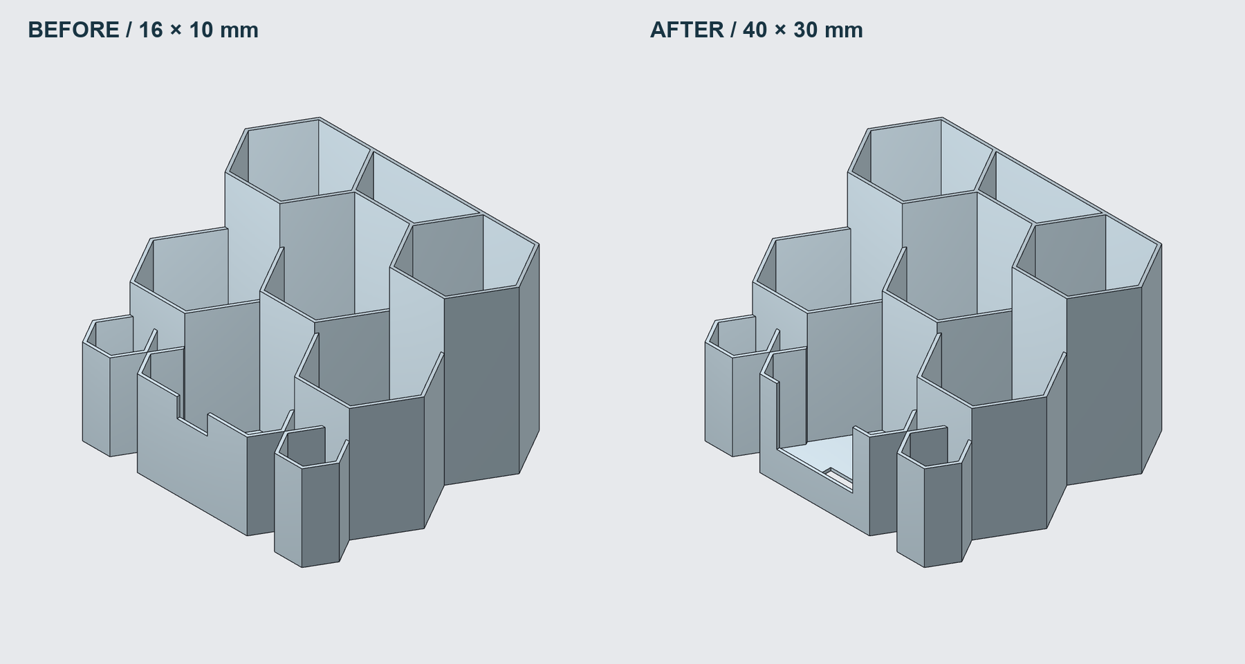
The useful result is a specific change in a continuing CAD document. That gives the next revision a clear starting point. Read more about working on the same model after AI generation.
3. Check what “editable” means for your part
Try the change you actually expect to make later. Can you adjust the relevant feature or face? Can you inspect its size? Does the saved project reopen with the result intact?
Different kinds of CAD data support different editing workflows. A native feature history may expose dimensions directly. Imported solid geometry may call for face edits or new features. A triangle mesh can be modified too, but it does not automatically provide the original design parameters.
The practical test is whether the available controls support your next change. Save, reopen, and check the important values before treating the model as your working source.
4. Review the handoff to your next tool
Choose the export for the next job. STEP is commonly used to transfer CAD geometry between systems; STL carries a triangle mesh commonly used for slicing. Neither the filename nor a successful download confirms that the receiving application has interpreted everything as intended.
Open the file in that application and check:
- Overall size and imported units.
- The number of bodies or separate parts you expect.
- Small openings, thin walls and curved surfaces.
- In the slicer, the layer preview around the features that matter.
STEP transfer should not be assumed to recreate the original application's complete feature history. Keep your editable source project alongside the export so that later changes have a reliable starting point.
5. Close the loop beside the object
For a large print with a critical fit, start with a short mating section or another small test piece. Measure what happened, record the adjustment, and revise that interface in the source model.
This is where mobile CAD in Nora3D becomes useful. You can inspect the model on a phone or tablet near the object, compare the feature with a measurement, and formulate the next change while the problem is in front of you. A larger screen can take over when the edit needs more room.
The aim is a shorter path between observation and revision: “this cable catches here” becomes “widen this opening, keep the surrounding wall and mounting holes.”
Questions to ask before choosing an AI CAD workflow
Can AI CAD produce an accurate part?
Judge accuracy against named dimensions and relationships. Measure those in the model, inspect them after export, and check the printed interface when physical fit matters. A useful evaluation states what was checked and the result.
Is a good-looking preview enough?
A preview helps you inspect shape and arrangement. To judge a functional part, also check dimensions, editing controls and the downstream file. Use the second-edit test to see whether the model supports continued work.
What should I check about credits and export access?
Before choosing a plan, check which actions consume AI credits, whether manual editing remains available, and which export formats your plan includes. For Nora3D, consult current pricing and the plan shown in the app.
Where should I start with Nora3D?
Choose a small holder, spacer or organizer with a few clear requirements. Create it, inspect the important dimensions, make one bounded change, and save it. That gives you a manageable first test of the workflow.
Start a model in Nora3D with the measurements that matter to your project. Then give it a second instruction—and check what changed.