When you're putting together an electronics project, the mounting job sounds simple: hold the board above the base, leave openings underneath it, and give the whole assembly somewhere to screw down.
You can describe that job without knowing which CAD command comes next.
That is the starting point for this Nora3D example: a 90 × 60 mm electronics mounting tray with raised board supports, ventilation slots and separate mounting holes. Codex used Nora3D's native modeling tools to build it, handling the sequence of sketches and solid features.
The goal is to make your requirements the starting point. The assistant handles the construction steps; you inspect whether the resulting part answers the brief.
Start with what the tray needs to do
A useful brief could be:
Create a compact tray for an electronics module. Raise the board off the base, add openings below it, and leave four places to fasten the tray down.
For this example, that became a 3 mm base with walls rising another 18 mm, for a total height of 21 mm. Four internal supports provide board-mounting locations. Four holes outside the walls provide a separate way to attach the tray to another surface.
Give each detail a practical job
A place for the board. Four raised standoffs establish the board's support points above the tray floor. Each has a 9 mm outer diameter and a 3.2 mm through bore, so the support and its fastening opening are both defined in the CAD model.
A place to secure the tray. The base extends beyond the surrounding walls. Four 4.2 mm mounting holes sit on that exposed area, keeping the tray's attachment points separate from the board supports inside.
Openings beneath the electronics. Four 4 × 24 mm slots pass through the floor. They give the design defined ventilation openings while retaining the surrounding base.
| Your design requirement | Structure in this example |
|---|---|
| A compact mounting footprint | 90 × 60 mm base |
| Raised board support | Four standoffs, each with a 3.2 mm bore |
| Attach the tray to another surface | Four 4.2 mm mounting holes |
| Openings below the board | Four 4 × 24 mm slots |
| A surrounding edge | Walls 18 mm above the 3 mm base |
These are decisions a maker can reason about directly: where the board rests, where the screws go, and which areas need to stay open. In this workflow, the assistant takes care of turning those decisions into the construction sequence.
The CAD work still happens. You can see it.
Nora3D built the tray from actual sketches and solid features. The rectangular profiles, circular holes and board supports remain represented in the model's history.
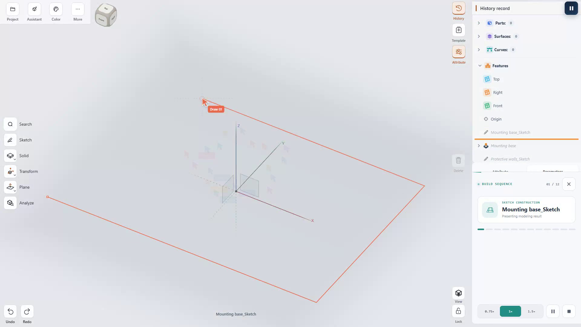
That is the useful shift for someone who wants a functional part: you can start by explaining the object and its dimensions. You do not have to manually perform this example's sequence of sketch creation, solid construction and cuts. The resulting CAD document still gives you something concrete to inspect.
The completed tray retained six sketches and twelve history features. After saving and reopening, its geometry was checked as one valid, closed solid with an overall size of 90 × 60 × 21 mm. Playing the construction history returned it to the same final geometry and saved revision.
Keep your attention on the project
For your own electronics mount, begin with the board's dimensions and mounting-hole locations. Add the space needed for components, connectors and fastener access. Those details tell the design what it has to accomplish.
The next question becomes practical: does this layout give your project the mounting arrangement it needs?
If your requirements change later, the existing design gives you a place to continue. See how another Nora3D PCB carrier gained more headroom and a wider cable opening while keeping its mounting base.
Start with the job your part must do. Let the assistant help with the CAD work.