You're updating an electronics project. A new component needs more room under the cover. A wider connector needs a bigger cable opening. You also need to reach the board when it's time to change a wire or replace a part.
But the mounting base already has the footprint and board supports you want. You want to keep that work.
The brief: add a cover you can remove, make room for the new components, and keep the existing mounting layout.
We explored that need with a PCB carrier in Nora3D. An AI assistant used Nora3D's modeling tools to add the cover and supports, then revise their dimensions and the cable insert in the same document. The result is more space above the board, a wider cable opening, and the original base layout retained.
Start with the work you want to keep
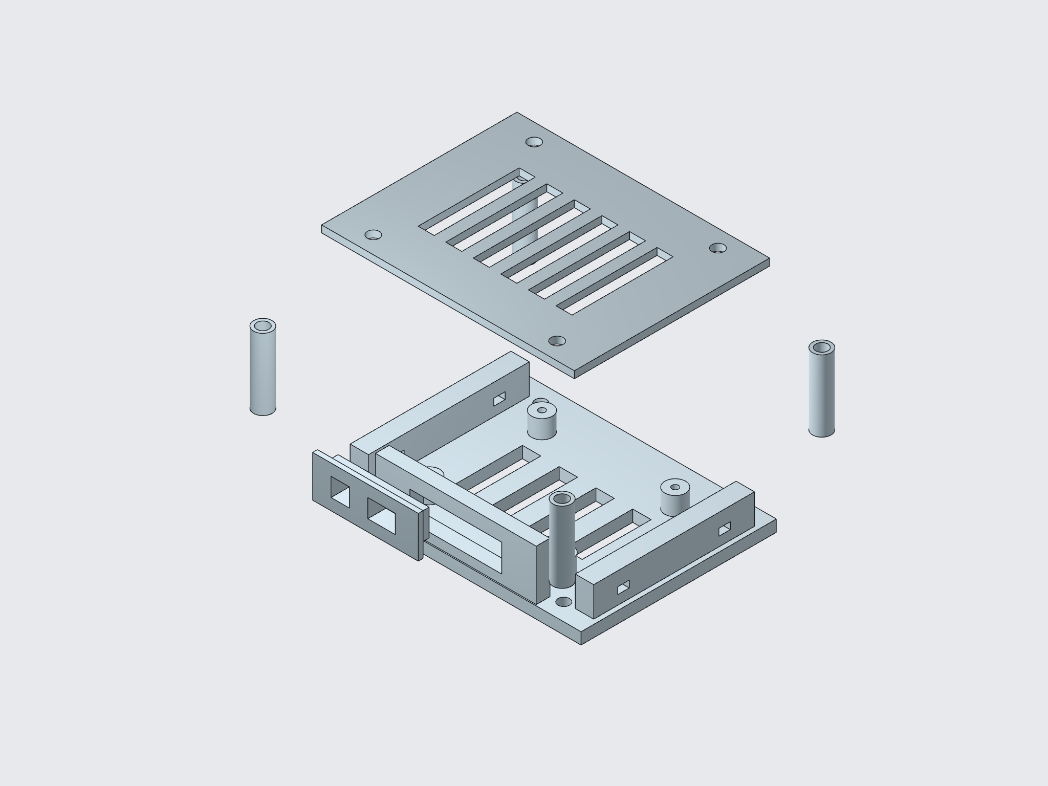
For this case, the starting point was a Ventilated PCB service carrier model. It already had a 110 × 85 mm base, board supports and mounting holes.
Those became the keep conditions. The AI-assisted workflow built around them, adding a separate slotted cover, four hollow spacers and a front insert with two cable openings.
That separation serves a practical purpose. You can work on the cover height without changing the board mounts. You can revise the cable insert without replacing the whole carrier. Each part has a job, and each change has a boundary.
More room above the board
A taller component changes the space you need. It also changes what must support the cover.
The assistant raised the cover's underside from 28 to 36 mm above the bottom of the base. It then lengthened all four spacers from 23 to 31 mm, bringing their tops to the cover's new position.
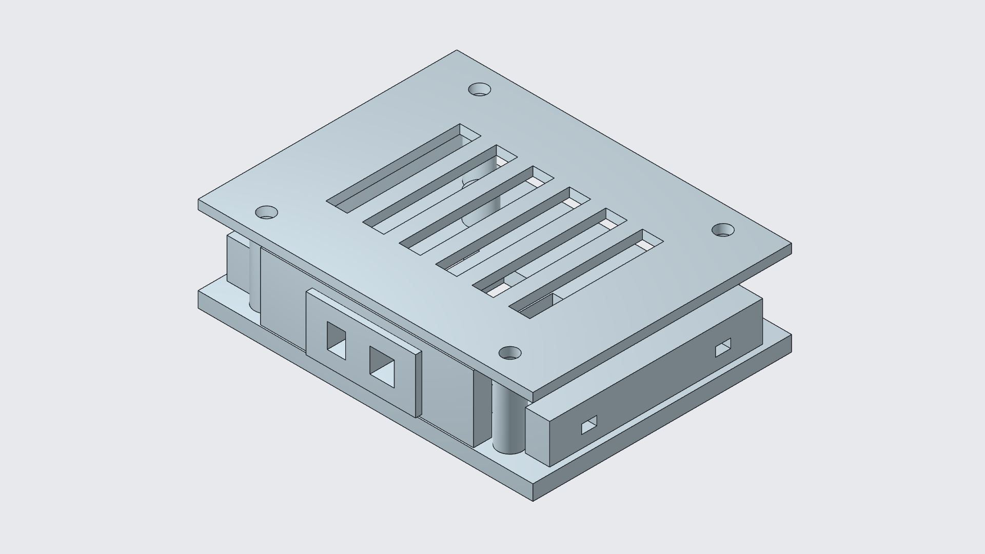
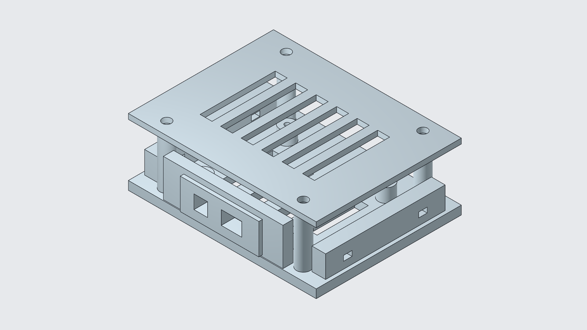
The base stays 110 × 85 mm. The board's mounting positions stay in place. The cover keeps its thickness, six slots and mounting-hole layout.
For the maker, that means the new height requirement is handled in the cover and supports. The mounting layout remains ready for the next revision.
A wider connector. A matching insert.
The second request reaches across two parts. Widen the carrier's opening, and the insert needs to change with it.
The assistant widened the window from 30 to 40 mm. It also widened the insert's plug section from 29.6 to 39.6 mm, preserving the 0.4 mm total horizontal design clearance. When centered, that leaves 0.2 mm on each side.
The outer flange grew with the insert. The two cable openings became 8 × 8 mm and 12 × 8 mm, with the smaller opening moved outward to make space for the larger one.
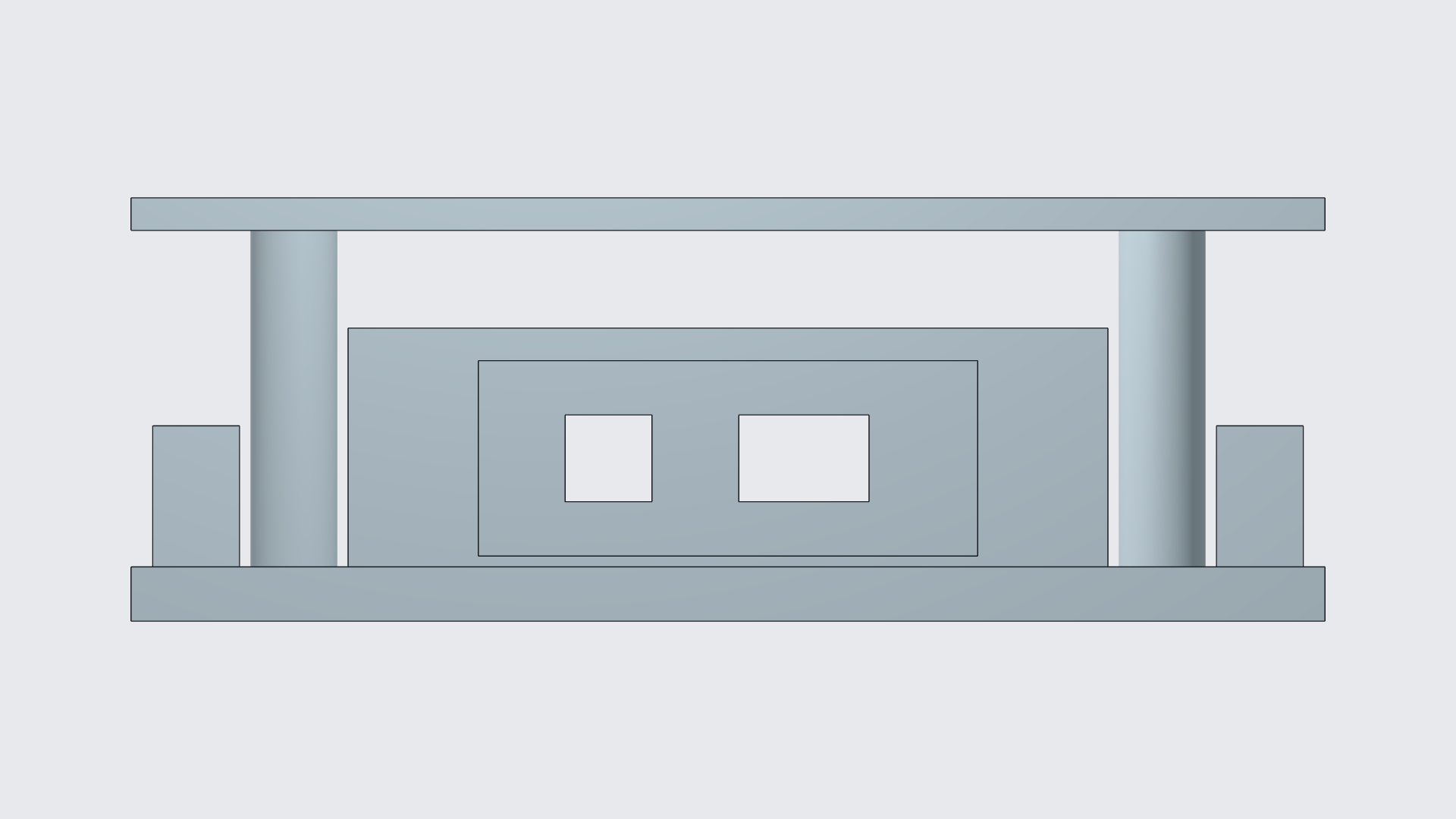
This is where AI assistance becomes useful in an existing design: it carries a requirement through the related CAD edits. Here, the assistant changed several features and checked their dimensions against the same brief. The wider opening, matching insert and retained clearance can all be inspected in the model.
Keep control of the result
The job ends with a design you can check and keep working on. After saving and reopening this model, geometry checks confirmed the revised cover height, spacer lengths, window width and insert width.
| Your requirement | What changed | What stayed |
|---|---|---|
| More room above the board | Cover height 28 → 36 mm; spacers 23 → 31 mm | Base and PCB mounting layout |
| A wider cable connection | Window 30 → 40 mm; insert plug 29.6 → 39.6 mm | 0.4 mm total horizontal design clearance |
| Access for later work | Separate cover and cable insert added | Existing carrier as the foundation |
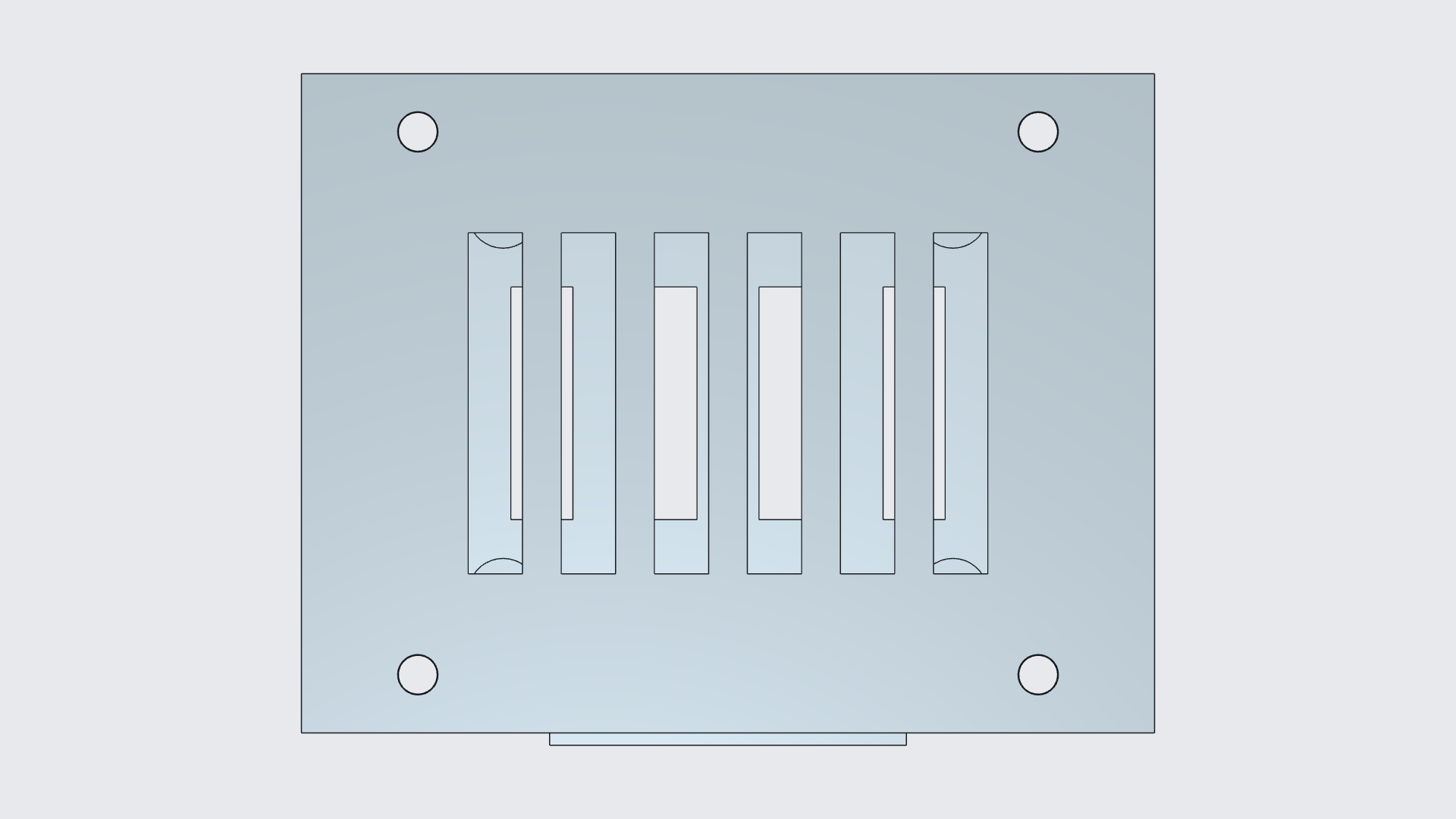
The added features remain editable in the same Nora3D document. If the next revision calls for another height or another opening, there is an existing design to continue from, with the previous dimensions available to inspect.
Your project moves forward. The work you wanted to keep comes with it.
For another example, see how a display cutout was resized while keeping the enclosure.