You have two round ducts with different openings. What you need is a transition between them—a part shaped around the two ends and the space available. A custom duct adapter starts with those requirements, before you decide which CAD commands to use.
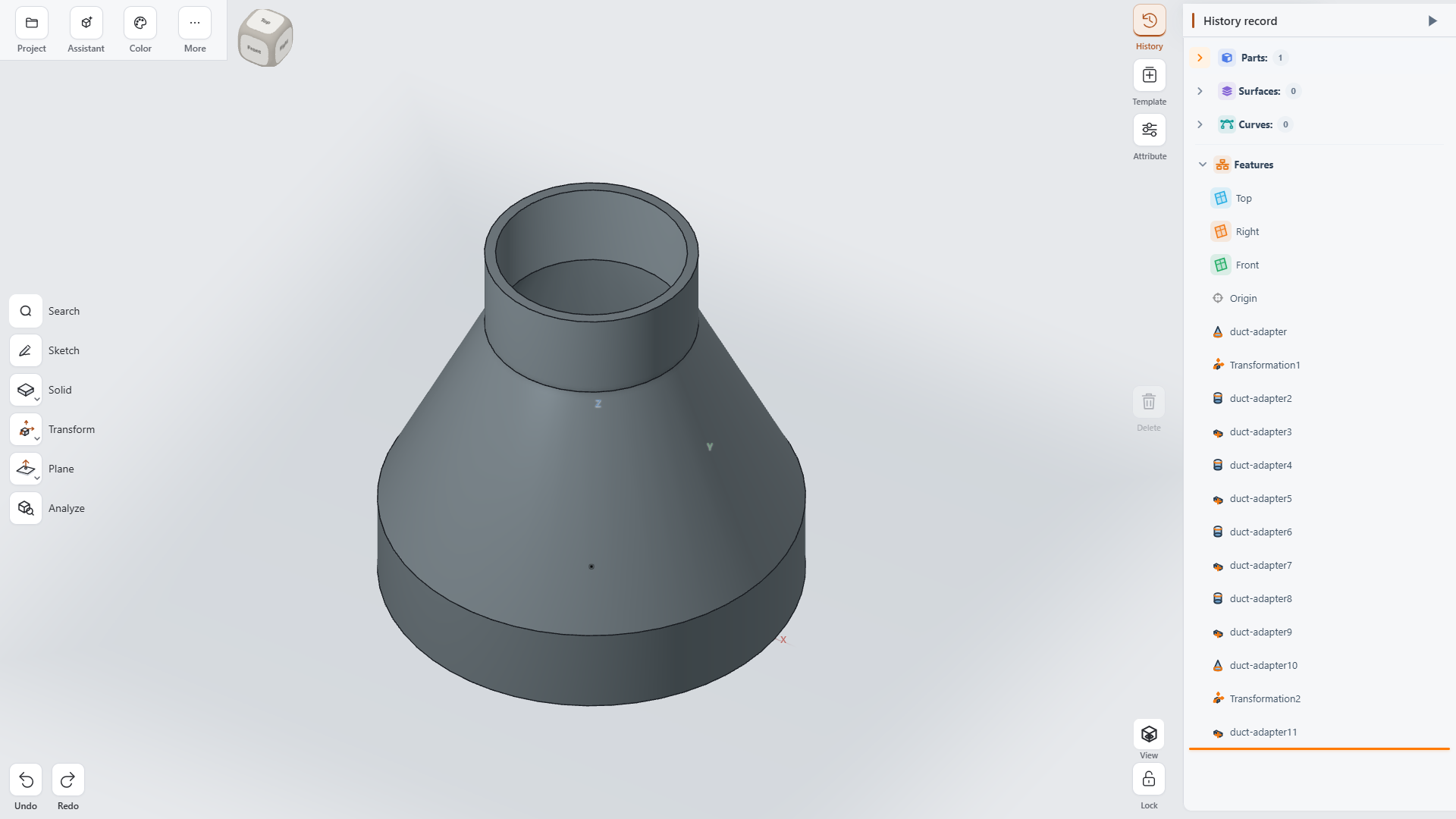
This Nora3D example turns that dimensional brief into a saved CAD model using an existing duct-adapter template. The larger bore input is 110 mm, the smaller bore input is 52 mm, and the transition-length input is 62 mm. Nora builds the template's solid features into a hollow transition that you can inspect in the workspace.
The useful shift is simple: begin with the part you need, rather than a list of modeling operations to learn.
Start with the connection, not the commands
Imagine a small workshop project where the two pieces of ducting you want to connect have different sizes. Your first questions are practical: what are the two mating surfaces, how should they overlap, and how much room is there between them?
Those questions form a useful design brief. They also make measurements more useful. An outside diameter describes a different surface from a bore diameter; deciding which surface must fit inside the other tells you which dimension to specify.
For this example, the template was supplied with three inputs:
| Design input | Value used | What it controls |
|---|---|---|
| Larger bore | 110 mm | The larger end of the template |
| Smaller bore | 52 mm | The smaller end of the template |
| Transition length | 62 mm | The tapered section between the ends |
These are the template's input values. The transition length describes the tapered section, not the full height including both end sections.
Let the template handle the construction sequence
Nora's native modeling workflow used the existing adapter template to create a new part. Its construction history contains 13 solid features. The result includes a wide end, a narrowing middle and a smaller end, with the opening visible in the finished model.
You can watch the model's construction below:
For a maker who already knows the required sizes, that is a useful division of work. You supply the connection requirements and choose the dimensions; the template supplies the modeling sequence. You do not have to manually repeat every solid operation just to produce this version of the adapter.
Keep a CAD model you can inspect
The output is a saved CAD document with its construction history. In this example, the model was saved and reopened, and playing its history returned it to the same geometry and saved revision.
That matters because a picture is only one way to judge a functional part. In the workspace, you have the model itself and the steps behind its shape. You can return to the design as you work out the details of your connection.
The same needs-first approach applies to other projects. In this electronics mounting example, the useful question was how to make room for changed electronics while keeping the mounting base.
Bring Nora the dimensions that matter
For your own adapter, begin with the two ends: their measured diameters, which surfaces should mate, the overlap you need, and the available space. Include how you intend to hold the connection together. These details describe what a useful part must do.
You should be able to spend more attention on that problem and less on remembering the next CAD command. This example shows a concrete starting point: choose an existing functional template, supply its dimensions, and inspect the resulting CAD design.
Start with the connection you need to make.