For 3D printing shrinkage compensation, first identify what is wrong. If several dimensions show a consistent proportional error, investigate a material or process correction in the slicer. If the outside dimensions are right and only a hole is tight, investigate that hole. Intentional fit clearance belongs in the design.
Imagine a printed mounting plate. Its outside edges land where they should. Its mounting holes line up. But the central bore is too small.
Scaling the entire part may open that bore—and move the mounting holes that already worked. Before changing a percentage, decide what must stay put.

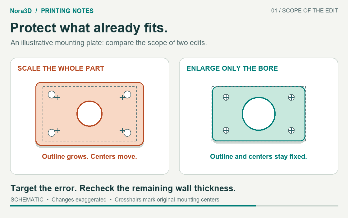
The tempting fix changes more than the hole
A global scale factor acts on every dimension along the scaled axes. The bore grows, but so do the outside dimensions and the distances between hole centers.
A local edit has a different scope: enlarge the central bore while holding the outside shape and mounting centers fixed. That also removes material around the bore, so check the remaining wall thickness.
Choose between two kinds of correction:
- Process correction: compensate a repeatable printing bias while retaining the intended CAD geometry.
- Design change: add the clearance the mating parts actually need.
OrcaSlicer provides separate controls for XY holes and outer contours. Their scope differs from scaling the entire model. Review the sliced geometry after a change. OrcaSlicer precision settings.
Let the measurements choose the correction
Compare several relevant dimensions, not just the one that failed. A useful measurement log includes the nominal size, printed size, axis, material/profile, orientation and time after printing.
| What you observe | What to investigate first |
|---|---|
| Several lengths are small by a similar percentage | Scale-related process error; material shrinkage compensation after calibration |
| Outside dimensions are acceptable, but holes are consistently small | Hole-specific process compensation |
| One interface needs intentional extra room | The relevant CAD clearance or bore dimension |
| Error changes with orientation or nearby geometry | A representative test piece and process review |
A similar percentage suggests a proportional pattern; it does not, by itself, prove material shrinkage. Confirm the printer and filament setup before compensating.
OrcaSlicer's tolerance calibration workflow uses test geometry and measurements to tune the relevant controls. A single successful adjustment is not a universal profile for every part. OrcaSlicer tolerance calibration.
When the evidence supports scaling, use the right percentage
Consider this hypothetical calculation, with no existing compensation:
| Nominal length | Measured length | Measured ÷ nominal |
|---|---|---|
| 80.00 mm | 79.60 mm | 99.5% |
| 40.00 mm | 39.80 mm | 99.5% |
Assuming this proportional behavior repeats, the inverse scale multiplier is:
80.00 ÷ 79.60 = 1.005025…, or approximately 100.503%.
There are three different numbers here:
- 0.5%: the dimensional loss.
- 99.5%: the retained-size ratio.
- 100.503%: the inverse scale percentage.

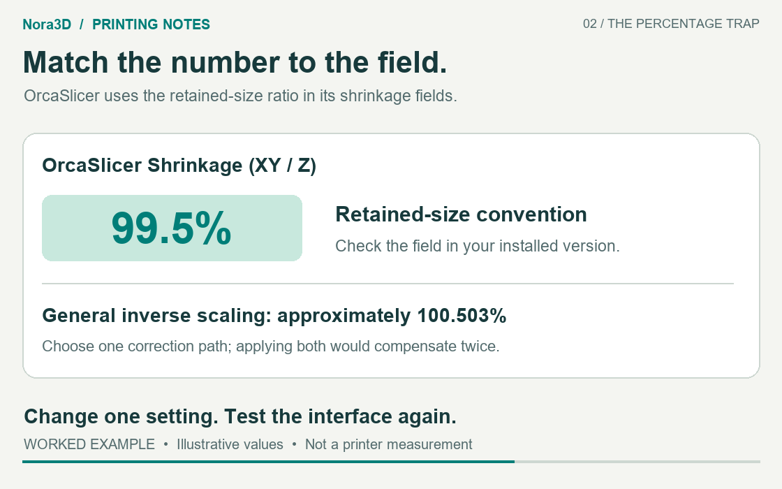
The input field matters. OrcaSlicer's documented Shrinkage (XY) and Shrinkage (Z) controls use the retained-size percentage: the documentation's example uses 94% when a nominal 100 mm measures 94 mm. Under that convention, the illustrative measurements above correspond to 99.5%, not 0.5% or 100.503%. Check the wording in your installed version. OrcaSlicer material settings.
Use one appropriate correction method for the next test. Applying the retained-size setting and the inverse model scale together would compensate twice.
Prove the change on the interface
Make the next test answer one question: did the intended interface improve while the dimensions you wanted to preserve remain acceptable?
- Use a small representative section containing the critical bore, slot or mating feature.
- Keep its relevant orientation, walls and print profile consistent.
- Change one correction layer.
- Measure again using the same method and timing.
- Check the complete part before treating the result as final.
For intentional clearance, define the quantity precisely. A 25.00 mm shaft and 0.30 mm diametral clearance imply a 25.30 mm bore; that is 0.15 mm per side. Choose the clearance for your actual mating parts and print process.
Prusa's design guidance emphasizes that suitable clearances depend on geometry, orientation, calibration and material, and that iteration is part of developing a printable design. Modeling with 3D printing in mind.
Give AI a bounded edit
A useful illustrative request is:
Enlarge only the central bore. Keep the plate outline and mounting-hole centers unchanged. Show the resulting bore diameter and remaining wall thickness.
Add your actual measured dimensions and chosen design clearance before using the request.
This is where editable CAD helps: the next adjustment has a specific target and explicit constraints. Nora3D's text-to-CAD workflow centers on generating a starting solid and continuing to refine it. Its mobile CAD workflow also supports reviewing and refining a design away from the desktop.
Quick answers
Should I enlarge every model by a fixed percentage?
Use measurements from your printer, material and relevant geometry. A blanket scale changes dimensions that may already be correct.
Can changing a hole affect the part's strength?
It changes the surrounding material. Recheck wall thickness and the design's load requirements; dimensional fit alone does not establish strength.
Should I keep the native CAD file after exporting?
Yes. Keep the editable source for later revisions. STEP transfers solid geometry but generally does not reconstruct the original native feature history; STL is a mesh for downstream use. Editable CAD and exports.
Keep the next edit focused
Start with the dimension that needs to change—and name the geometry that must stay. For a broader review checklist, read How to Trust AI CAD for 3D Printing. To follow an editable-model workflow, see Keep Working on the Same Model.