Need more room to position a motor mount? Extend its mounting slots while keeping the motor interface where it is. In this Nora3D example, two base slots grow from 28 to 40 to 48 mm. Their width stays 6 mm, and the upright plate, central opening and four motor mounting holes remain in place.
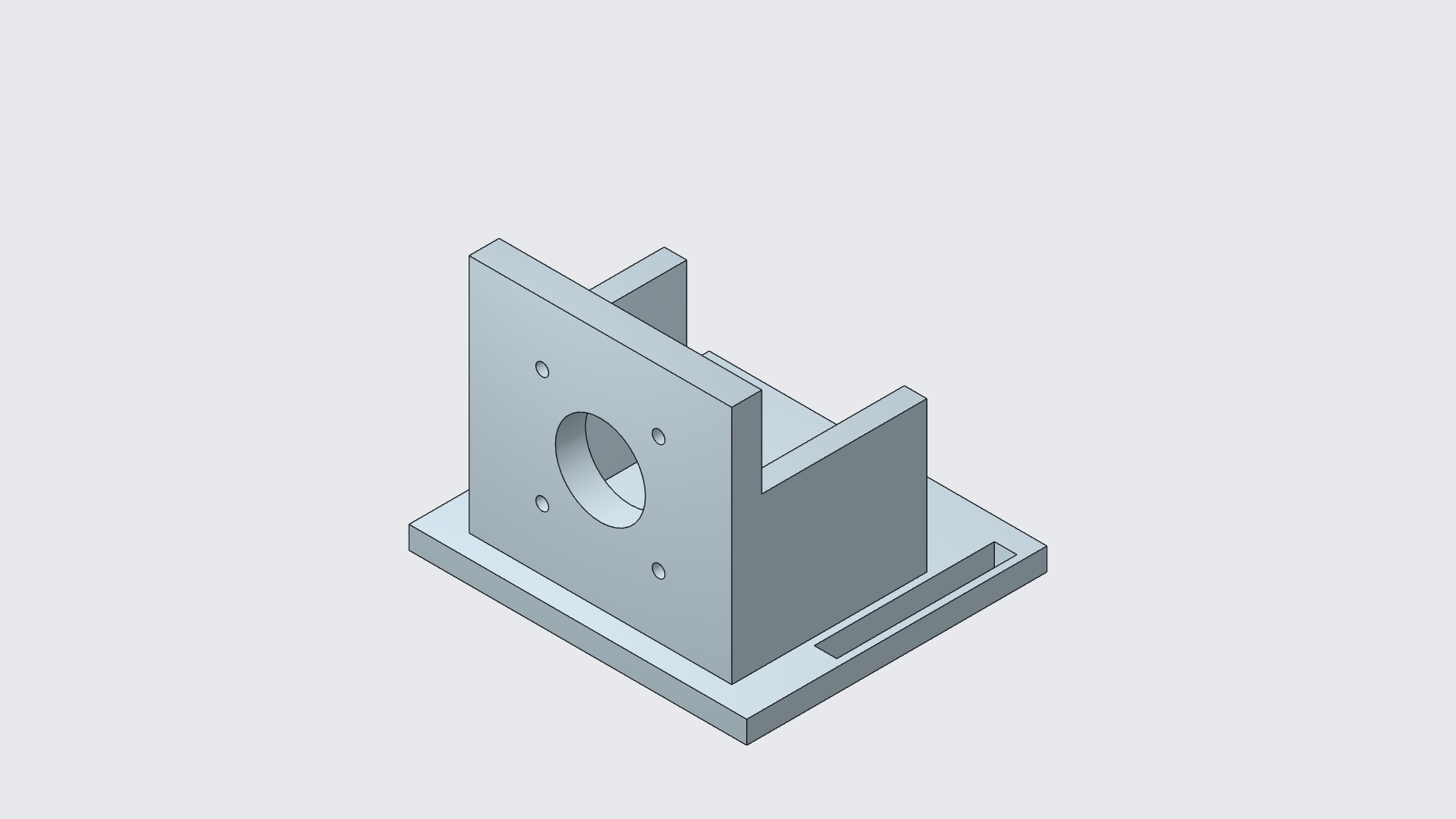
Change the adjustment range, not the motor interface
A motor can have the right mounting pattern and still need more room to move along a machine base. For a belt-driven layout, that positioning range is a separate design decision from the holes that attach the motor.
Our starting point is the Slotted motor angle mount from Nora3D’s template library. It already has an upright mounting plate, a central opening, four small mounting holes and two side supports. The two rectangular base slots are the part we want to change.
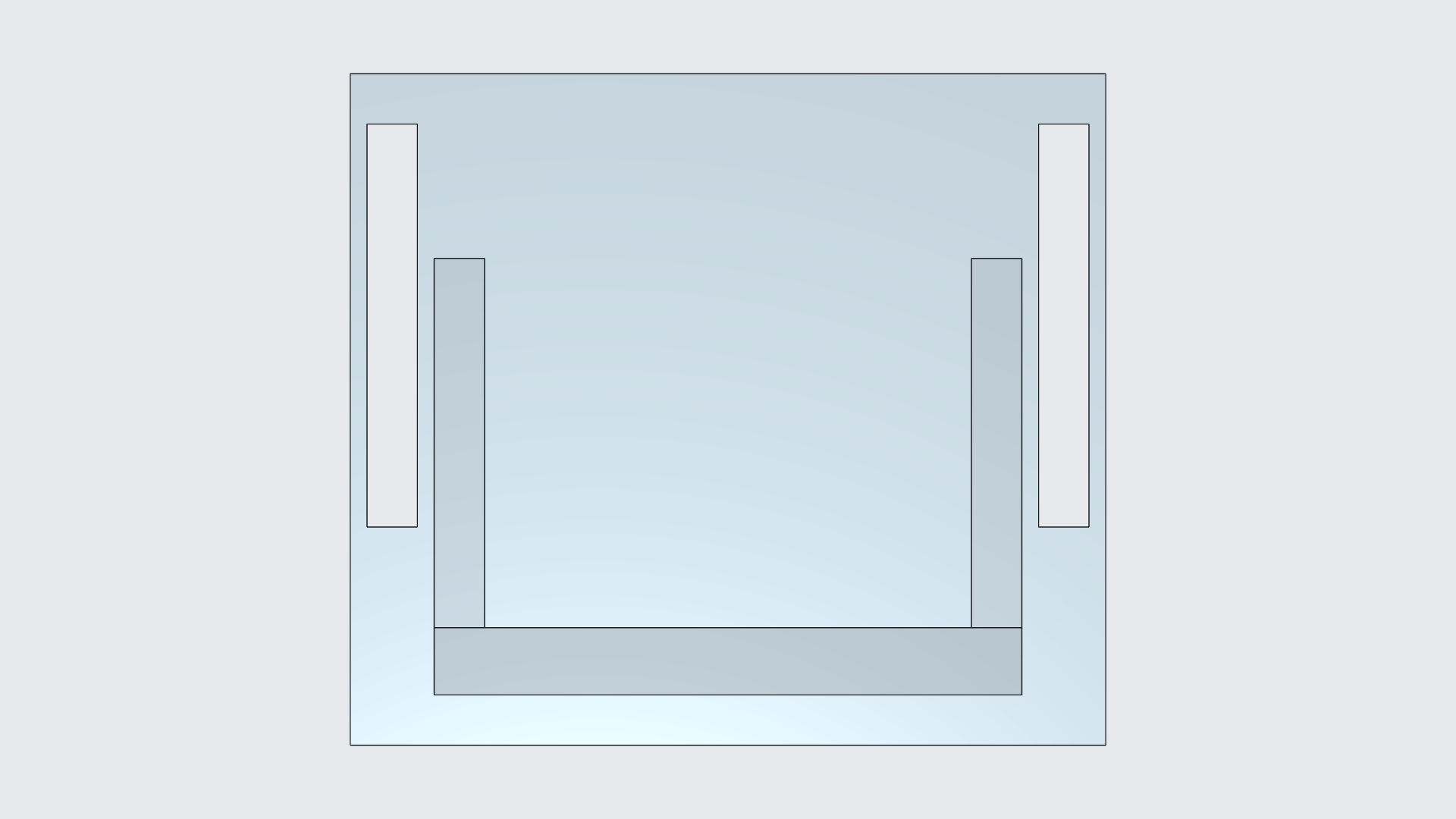
The goal is to extend both slots toward the upright plate. Their opposite ends stay put. The base stays the same size, so the edit adds adjustment room without scaling the whole bracket.
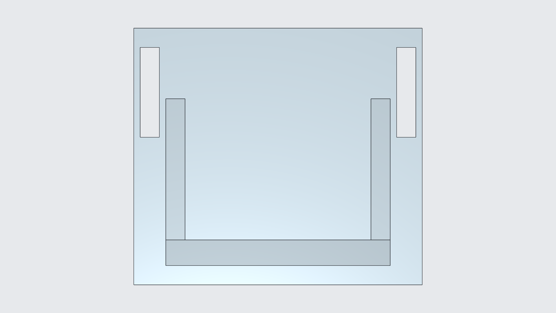
First, add 12 mm where the slots stop
We added a sketch and a cutting feature to the inserted template. The sketch defines the two 6 × 6 mm slot-end sections; the cut extends them 12 mm into the base. Both slots become 40 mm long, with the same 6 mm width.
The useful control is now the extension depth. It changes how far the slots reach toward the upright plate, rather than changing the motor mounting pattern or making the entire part larger.
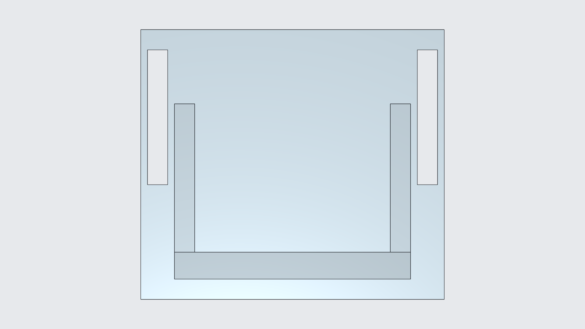
Need another 8 mm? Refine the same feature.
For the next layout target, we increased the extension depth from 12 to 20 mm. The same cutting feature recalculated, and both slots became 48 mm long. There was no need to rebuild the mounting plate or redraw its holes.
| Design stage | Added extension | Each slot | Motor interface |
|---|---|---|---|
| Library template | 0 mm | 28 × 6 mm | Starting geometry |
| First adjustment | 12 mm | 40 × 6 mm | Retained |
| Refined adjustment | 20 mm | 48 × 6 mm | Retained |
Slot length is not the same as usable bolt travel: the bolt diameter and the clearance you leave at each end also matter. Choose the range for your actual assembly. Gates’ drive-design guidance likewise describes a slotted adjustment by its start and end positions along the movement path. Gates PowerGrip drive design manual, printed page 175.
Keep the work you already have
The saved model was reopened and measured again: both slots remained 48 mm long, and the checked slot width remained 6 mm. The final model retained the 24 mm central opening, four motor mounting holes and the original outer envelope.
The template supplied the starting solid. The sketch and editable extension were added in this workflow; they do not depend on recovering the template’s original construction history. That is the value of continuing with the same model: the next requirement becomes a focused change to useful work you already have.
For a checklist to carry into your next change, read how to review a functional CAD design.