If an AI-generated 3D model loses walls, develops gaps, or fills a cavity in the slicer, check three things first: the geometry, the final dimensions, and the generated toolpaths. Repair open or invalid mesh boundaries, revise details that have become too thin, and inspect the affected layers again. A good-looking render alone cannot tell you which of those checks will fail.
For functional parts, the useful question is what needs to change while the rest of the design stays intact. That is where editable CAD becomes valuable: you can work on the wall, opening, or connection that causes the problem.
Start with the symptom, not another export
Meshy's own slicer troubleshooting guide identifies thin walls, open edges, and intersecting surfaces among the issues that can appear in generated models. They need different responses.
| What you see | What to check first | Useful next move |
|---|---|---|
| A wall vanishes in layer preview | Its thickness at the final size; active perimeter settings | Adjust that wall or the relevant slicing settings, then compare the layers |
| Pieces that should connect remain separate | A real gap, a tiny contact, or unintended separate bodies | Define the intended connection in the model |
| A cavity becomes filled | Mesh boundaries, face orientation, repair changes, and slicing mode | Compare the original and repaired geometry before accepting the result |
| A non-manifold or open-edge warning appears | The affected mesh edges and surrounding surfaces | Repair the local defect or rebuild the feature |
Keep a copy before repair. If a warning disappears but an important opening closes, the repair has changed the design you meant to make.
Scaling down also scales the wall
A maker reported gaps after reducing an AI-assisted ornament's size. That report raises a useful question to ask of any model: what happened to its smallest features when its overall dimensions changed?
For a simple uniform-scaling example, reduce a 125 mm-wide design to 75 mm. The scale factor is 75 ÷ 125 = 0.60. A 0.80 mm wall becomes 0.48 mm. Small connectors and clearances also become 60% of their original dimensions.
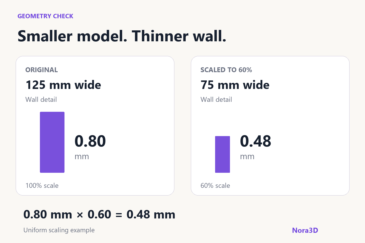
The calculation does not establish whether 0.48 mm will produce a suitable wall on your machine. Prusa's Arachne documentation explains that variable-width perimeters can adapt to thin features, while minimum feature-size settings can still exclude them. Check the actual toolpath with your nozzle, material, and profile.
If the outside dimensions must stay at 75 mm, scaling the whole object back up changes the requirement. Consider a local wall or connector revision instead, and check what that revision does to the usable space inside.
Check what is connected—and what should stay separate
For a closed triangular boundary around a solid, each edge should belong to two triangles. An edge belonging to only one triangle indicates an open boundary; an edge shared by more than two is a non-manifold example. Face orientation matters too. These requirements are set out in the 3MF Core mesh specification.
Then check design intent. Two valid solids can still be separated by a gap. Point or edge contact can create a zero-thickness connection. A shared face may support a valid union, so “the parts touch” is not enough information to decide what to do.
For one continuous part, inspect the resulting connected volume after joining. For a multicolor part, preserve the intended material regions and verify their assignments in the slicer. Joining every body indiscriminately can remove distinctions you wanted to keep. There is no universal overlap value that fixes every design.
Repair the mesh, or revise the feature?
Mesh repair makes sense when you want to retain a sculpted surface and the problem is a local boundary defect. A functional wall, mounting hole, or clearance often benefits from a dimensional edit instead.
In Nora3D, the same-model workflow combines AI requests with manual CAD editing. Use a bounded request that names both the change and the geometry to preserve. For example:
Increase the left wall inward to 1.2 mm. Keep the outside width, base thickness, and mounting-hole positions unchanged. Show the resulting internal width before I export.
Choose the value for your own design and printing process. After the change, inspect the wall and the preserved features. A request describes the intended outcome; the resulting model is what you need to check.
This is also a useful phone or tablet CAD workflow: compare the model with the object on your bench, note a measured dimension, and specify the local change. Keep the intended physical fit tied to measurements rather than the appearance of a render.
STEP, STL, or 3MF: choose for the next task
STEP carries CAD geometry for exchange and further editing. An imported STEP model does not automatically recover the original application's feature history; our STEP editing guide explains the distinction.
STL carries a triangulated surface. Exporting to STL does not itself join disconnected pieces, add wall thickness, or correct the design.
3MF can describe multiple objects and material properties in a printing workflow. Its capabilities depend on what the exporting and receiving software support; choosing it does not guarantee valid geometry. The 3MF Core specification defines those structures.
Nora3D lists STEP and STL among its supported export options. Keep the editable source, choose an export your next tool supports, and confirm the imported dimensions before slicing.
Inspect the layers where the design could fail
Move the layer slider through the thin wall, the start of a cavity, and the connection between regions. Check that the expected paths exist and that openings remain open. Review support and orientation where geometry begins above the build plate.
Before a long print, consider a small, representative test of the critical fit or connection using the intended material and orientation. Prusa's design guide emphasizes iteration and explains why fit tolerances depend on geometry, settings, calibration, and material.
The next useful version is the one that resolves the specific problem while preserving the rest of the part. Keep that editable version so the next adjustment can build on it.